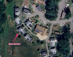
When we were designing our cohousing community, we made a lot of effort to make sure all the buildings had decent southern exposure so we could add solar panels later on. And over time, many of us did. My house in particular has 4.9kw of solar on the roof, grid-tied to offset our consumption.
But I’m finding the grid tie system unsatisfying. While it’s helping lower our electric bills, given the consumption of the house, the 15-20kWh generated by the panels (on a good day!) isnt’ really enough to offset the 80kWh per day we can hit during the winter (minisplits – great air conditioners – only mediocre heaters).
And then of course there’s the fact that grid-tie systems do not actually provide ‘power backup’. They generate power only when the sun is shining, and that power is ‘mixed’ into the power draw for the house. If the grid goes down, the solar panels are automatically disconnected. Everything goes dark, as it were. There’s no storage mechanism, and no ‘power backup’. While I understand why not (battery / storage / backup systems are complex and expensive), I still feel like it’s something I should have, or at least understand.
The Beginnings of a Project
A few years ago my Makerspace picked up a stack of discarded solar panels. We tested them, they were 36volt 305 watt panels, and best of all, they were free for the taking. I decided to see if I could build my own ‘off grid’ solar installation. I’d start small, with pretty limited capacity – the goal was to be able to power my shed, which has all my tool batteries, lighting, sound when I’m working, and my power tools when doing anything requiring 110v power (like the grinder or lathe). Most of my tools are battery powered, so having a charging station that’s driven from solar panels was appealling.
The first step was I basically had to learn all the terminology and all the components in a battery backed solar power station.
The basics are easy. What are volts and amps and watts. Each of these terms is important to understand, because you have to take them into account when designing a system. Volts, Amps, Watts, kWh… most of this is pretty basic. The biggest challenge for me was understanding that ‘kWh’ is basically the measure used to describe how much battery storage was available, and what sort of power you’d need to provide over time.
My panels are operating at 36v, and are rated to produce 305 watts of power, W = V*A, or 305 = 36 * A, or roughly 8.5A of current. That’s a pretty good start. In reality, these panels won’t produce anything close to that. After installation, they appear to top out around 200w/panel in perfect conditions.
Now. Wattage can be used to describe how much work is happening. For instance, a 100watt bulb is using 100watts of power (doesn’t matter what the voltage is, 100w is 100w). Why is this useful? Because capacity in a solar power system, and power consumed in a day are both defined via ‘Kilowatt-hours’ – or basically how much power is used in hour. That 100 watt bulb would use .1kwh if left on for an hour. If my batteries had a 5kwh capacity, that bulb could stay running for about 50 hours from a set of fully charged batteries.
Putting the Pieces Together
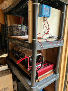
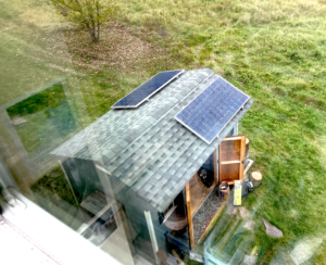
I started out very modestly on my shed project. I picked up one of the solar panels from the makerspace, mounted it on the roof of the shed, and ran lines into the shed to the controller. I purchased a relatively lightweight MPPT and wired it in.. These are relatively low cost devices that act as a bridge between the solar panels and your battery bank, and prevent the batteries from over-charging. Here’s a good definition:
An MPPT, or maximum power point tracker is an electronic DC to DC converter that optimizes the match between the solar array (PV panels), and the battery bank or utility grid. To put it simply, they convert a higher voltage DC output from solar panels (and a few wind generators) down to the lower voltage needed to charge batteries.
https://www.solar-electric.com/learning-center/mppt-solar-charge-controllers.html/
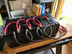
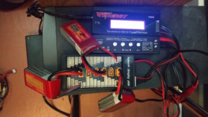
Now I had a power feed, but I needed batteries. Through a ridiculous series of events, I managed to purchase 6 24v 20Ah Lithium Iron Phosphate (LiFePO4) batteries for an extremely good price. That’s .480kWh per battery, or 2.8kWh of battery storage. That’s good for a starting point. These batteries are pretty much the standard style for solar installations, though you wouldn’t usually use a bank like this, you’d get one or two extremely large ones (these are about the size of a lunchbox each).
Next step is making that 2.8kWh of 24v power available for use. In the past, using inverters to convert the power from one voltage to another was an extremely wasteful process. But modern inverters are pretty good. I got an extremely cheap 1kw inverter off Amazon that was designed to take 24v and wired it to the battery bank directly. This gave me 120v power running off a set of batteries that are charged exclusively from solar. I was in business.
At this point, it’s important to note that while this all sounds pretty clean and straight forward, there’s a lot of wiggle room to consider. For instance, solar panels are not perfect – not even close. They only produce power when there is sunlight on them. Here in the northeast, that’s not a big part of the day. On a good day I could get 4 or so hours of direct sunlight in the winter. My little single 305w panel was absolutely not going to be able to keep up. I added a second panel, and wired them in parallel (which would double the amperage, but keep the voltage the same). Now I’m doing on a good day about 1.7kwh of power. If my batteries get completely drained, it’ll take a day and a half to refill them. I’ll definitely need more capacity, but I’m not using the batteries for a lot right now, so this is fine.
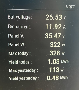
The solar controller I’m using has a bluetooth module that lets it be monitored remotely, but given that this is out in tool shed, and data is available from it only when the phone is attached to it, I needed something a little more realtime. I hooked up a raspberry pi to the controller and set up a small python script to constantly poll the controller for telemetry, which then posts to MQTT. I then added an MQTT polling function to my Magic Mirror – giving me a realtime display of what was happening in the power shed, including maxes for the last 2 days.
Up And Running – And Next Steps
So far this has been a stable, successful project. Of course, once it was up and running, winter set in, so I spent less time out in my workshed, but I’m looking forward to having it ready for more use. One of the challenges is keeping things cool in the summer. The smallest AC I can find is about 4A@110v, or 440watts. On a sunny day, I can just barely keep up with that, but there’d be something awfully nice about having an AC cooled workshop that’s 100% solar powered.
I’m planning on upgrading the installation this summer to add 2-4 more panels, bringing my total production closer to 1kw. This will unfortunately push past the capacity for my MPPT controller, so that’ll need an upgrade. And of course, I’d love to figure out how to add more batteries fore capacity.
Ultimately I’d love to find a way to wire this into the house. Right now there’s no simple way to do this other than running an extension cord through a window and running some internal gear on it. Short of adding a new panel to house mains and putting a smart switch in place, I may simply need to live with having a secondary power source powering SOME things, separate from the house.
