I Built an Evil Genius Sign for Halloween

It’s no secret I’m a huge fan of Warner Brothers cartoons. My sister and I were basically raised on this stuff, and so much of our cultural reference points (and humor) comes from watching Bugs Bunny when we were growing up.

So, as Halloween approached, I thought it might be cool to recreate an iconic image from the 1952 cartoon “Water Water Every Hare”, where Bugs is taken to a big scary castle on the edge of a waterfall. The castle is inhabited by, naturally, an Evil Scientist, who advertises the fact with a blinking sign on the towers of his castle.

Okay, I’m not really a scientist, I’m an engineer, but I figure I could apply a little artistic license and make a sign like that for my house for Halloween.

I wanted it big enough so I could put it in an upstairs window and have it visible from the pathway. We get a LOT of kids through our community over Halloween, and tons of parents as well (since mostly the parents would get the reference), so it needed to be visible. In order to constrain the glare, I decided to put it in basically a shadowbox configuration. An enclosed box, LED lighting inside, with a cutout pattern on front that would show the text.

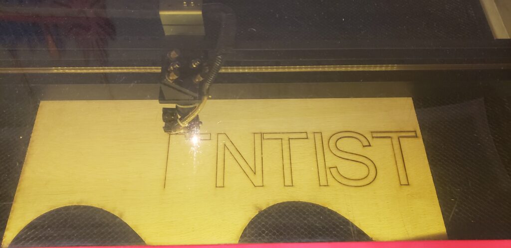
First step was to use the laser cutter at the Makerspace to cut out the lettering. As anyone who does stencils will recognize, the second line (“BOO”) would have floating elements in it, and would have to be glued down after the box was made.

I found some old acrylic sheeting that still had one strip of white backing on that, and that made a dandy diffuser, as well as a place to mount the center parts of the lettering.

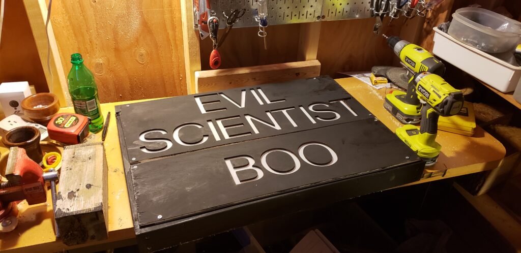
Next, based on the size of the lettering, I whipped up a box out of some scrap wood, and painted it black. I also painted the letter stencils so the shadowmask wouldn’t show up at night, but the lettering shining through would.

The colored lighting was done with some LED strips and an arduino. The sketch was painfully simple. Just first row on, wait a second, off, wait a half second, second row on, wait a half second, off, then wait a half second and then repeat. The most challenging part was soldering up the strips (I needed 3 rows), and mounting the arduino.

The only thing I had to go ‘buy’ was the backing board. A quick trip to Michaels got me a sheet of the plastic corrugated ‘cardboard’ for $4. This stuff is awesome, and I think I’m going to use it more in future projects. I mounted the LED strips and the arduino to it initially using hot glue, but while that’s the default ‘go to’ for DIY projects, I ended up ziptying the strips to the backing board, and doing the same for the arduino. Since the board is flexible, hot glue just didn’t make sense.

Once everything was screwed together, it was just a matter of putting it in the window and plugging it in. Yay! It worked!

I slightly misjudged the width of the window, so it doesn’t quite have the margins I had hoped, but when it got dark, it looked great. Very happy with the end result!

Arduino Nano “Programmer Not Responding” on a Mac

Arduino Nano v3
Arduino Nano v3

For the Staff project, I’m going to be replacing the existing Arduino Uno R3 with a smaller, more easily embedded Arduino Nano.  The Nano is a heck of a lot smaller than the Uno (makes sense – it’s meant to be permanently installed, while the Uno is a prototyping platform).  I received my Nano a few weeks ago, but immediately ran into a frustrating problem… code would compile, begin to upload, and I’d get the error “stk500_recv(): programmer not responding”

The intarwebz are full of people reporting this problem, unfortunately most are not finding answers.

I went through the usual debugging problems – changing out the USB cable I was using, checking to make sure USB drivers were correct – I could still upload and use code on my Uno, but the Nano flat out refused to accept the new code (and I did check the very common problem of not selecting the correct board in the IDE).

Finally, came across a general discussion about bootloaders, and there was a comment that sometimes these boards do not reset properly.  After some more research, I found some folks using various ‘reset button’ hacks to sort of nudge the board into accepting code.  With a lot of trial an error, I have a procedure that seems to work pretty consistently.  There’s occasional twitches, but with persistence it always loads.

Continue reading “Arduino Nano “Programmer Not Responding” on a Mac”

Video Demo of the Staff

Several people have asked how the project’s coming along, and I realized that the most recent video only showed a little bit of the functionality.  So I dusted off my iMovie skills and whipped up a little demo (complete with background music!  Aren’t you impressed?).  All the current modes are displayed, though the most recent one isn’t quite done yet.

Enjoy!

The Arduino Mini 05 is… well, mini!

Arduino Mini 05
Arduino Mini 05

I’m looking to replace the Arduino Uno in the staff with a smaller controller that will fit in the body of the internal tube. The Mini 05 seemed like the best option… well, received it this weekend, and I have to admit, I’m a little daunted.

On the one hand, it sure will fit in the staff, on the other hand, there’s a lot of very small contact points here. My soldering is pretty crude. I’ll have to put in a header for the USB port first, after that I can probably use a socket, which’ll make connections a lot easier.

Magic Staff – Batteries, load, and runtime

Another few hours of work this weekend saw the Staff cut loose from it’s moorings for the first time.

Staff
Staff running on batteries only for the first time

One of the biggest challenges on this project is power.  The LED strips are 55 tricolor (very bright!) LEDs driven by WS2811 controllers.  The strips are powered at 5v.  Doing some quick load testing on the initial strip (and some online research) showed that each LED has a maximum draw of 60mA, so a 55 LED strip can draw a max of  3.3A @ 5v, and 6 strips can draw something like 20A @ 5v if the entire thing is at full brightness.  That’s a heck of a lot of current.   Compared to that, the Arduino wouldn’t be drawing dink.

I had to balance battery capacity with weight (this thing is meant to be carried in one hand after all).  I considered using D cells, but they’re just too heavy.  I ended up with 8 NiMH C batteries ( http://www.amazon.com/gp/product/B001AX1UQO/ ) from Tenergy.  These are ranked at 5000 mAh @ 1.5v.  I ganged them in groups of 4, connected in parallel.  This gave me 5Ah per group, or 10Ah total.  With a draw of 20A, at full power, it works out to only half an hour of uptime.  Now, there’s a lot of loss in this as well, so realistically, at full power (255,255,255 values on all the LEDs) I expect to get only about 15-20 minutes of use.

In general use, I don’t plan on using this in BLAZING WHITE MODE for more than a few seconds at any given time, but ongoing running will run the batteries down.  The other night I ran the staff using a ‘randomized’ pattern for a good 15 minutes on those batteries without any ill effects, and saw no problems (Check out the video here:  http://youtu.be/LNbIwpk5vdA )