A Homegrown Off Grid Solar Installation

When we were designing our cohousing community, we made a lot of effort to make sure all the buildings had decent southern exposure so we could add solar panels later on. And over time, many of us did. My house in particular has 4.9kw of solar on the roof, grid-tied to offset our consumption.

’round home.

But I’m finding the grid tie system unsatisfying. While it’s helping lower our electric bills, given the consumption of the house, the 15-20kWh generated by the panels (on a good day!) isnt’ really enough to offset the 80kWh per day we can hit during the winter (minisplits – great air conditioners – only mediocre heaters).

And then of course there’s the fact that grid-tie systems do not actually provide ‘power backup’. They generate power only when the sun is shining, and that power is ‘mixed’ into the power draw for the house. If the grid goes down, the solar panels are automatically disconnected. Everything goes dark, as it were. There’s no storage mechanism, and no ‘power backup’. While I understand why not (battery / storage / backup systems are complex and expensive), I still feel like it’s something I should have, or at least understand.

The Beginnings of a Project

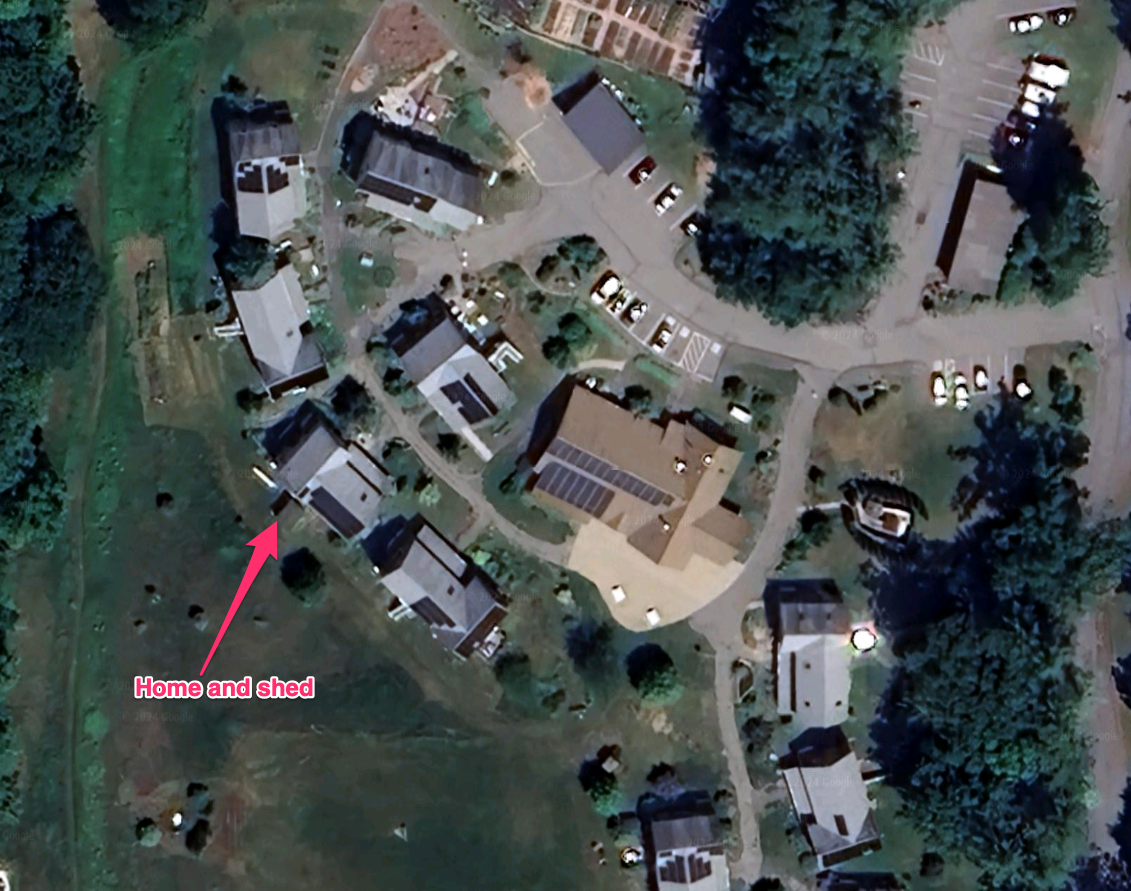
A few years ago my Makerspace picked up a stack of discarded solar panels. We tested them, they were 36volt 305 watt panels, and best of all, they were free for the taking. I decided to see if I could build my own ‘off grid’ solar installation. I’d start small, with pretty limited capacity – the goal was to be able to power my shed, which has all my tool batteries, lighting, sound when I’m working, and my power tools when doing anything requiring 110v power (like the grinder or lathe). Most of my tools are battery powered, so having a charging station that’s driven from solar panels was appealling.

The first step was I basically had to learn all the terminology and all the components in a battery backed solar power station.

The basics are easy. What are volts and amps and watts. Each of these terms is important to understand, because you have to take them into account when designing a system. Volts, Amps, Watts, kWh… most of this is pretty basic. The biggest challenge for me was understanding that ‘kWh’ is basically the measure used to describe how much battery storage was available, and what sort of power you’d need to provide over time.

My panels are operating at 36v, and are rated to produce 305 watts of power, W = V*A, or 305 = 36 * A, or roughly 8.5A of current. That’s a pretty good start. In reality, these panels won’t produce anything close to that. After installation, they appear to top out around 200w/panel in perfect conditions.

Now. Wattage can be used to describe how much work is happening. For instance, a 100watt bulb is using 100watts of power (doesn’t matter what the voltage is, 100w is 100w). Why is this useful? Because capacity in a solar power system, and power consumed in a day are both defined via ‘Kilowatt-hours’ – or basically how much power is used in hour. That 100 watt bulb would use .1kwh if left on for an hour. If my batteries had a 5kwh capacity, that bulb could stay running for about 50 hours from a set of fully charged batteries.

Putting the Pieces Together

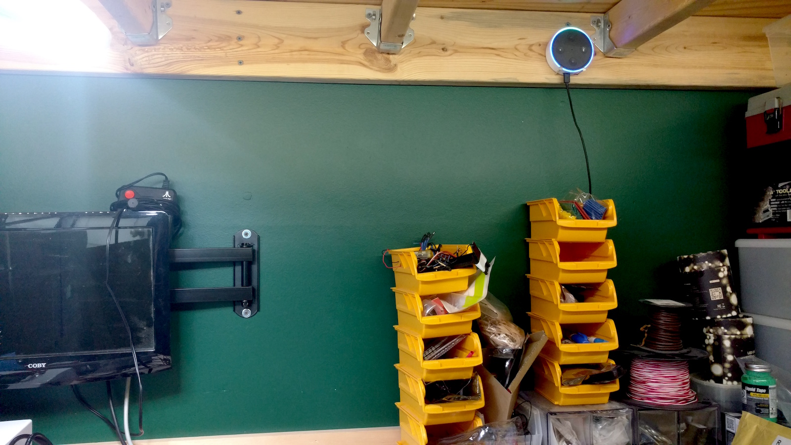
I started out very modestly on my shed project. I picked up one of the solar panels from the makerspace, mounted it on the roof of the shed, and ran lines into the shed to the controller. I purchased a relatively lightweight MPPT and wired it in.. These are relatively low cost devices that act as a bridge between the solar panels and your battery bank, and prevent the batteries from over-charging. Here’s a good definition:

An MPPT, or maximum power point tracker is an electronic DC to DC converter that optimizes the match between the solar array (PV panels), and the battery bank or utility grid. To put it simply, they convert a higher voltage DC output from solar panels (and a few wind generators) down to the lower voltage needed to charge batteries.

https://www.solar-electric.com/learning-center/mppt-solar-charge-controllers.html/

Batteries being wired up

Now I had a power feed, but I needed batteries. Through a ridiculous series of events, I managed to purchase 6 24v 20Ah Lithium Iron Phosphate (LiFePO4) batteries for an extremely good price. That’s .480kWh per battery, or 2.8kWh of battery storage. That’s good for a starting point. These batteries are pretty much the standard style for solar installations, though you wouldn’t usually use a bank like this, you’d get one or two extremely large ones (these are about the size of a lunchbox each).

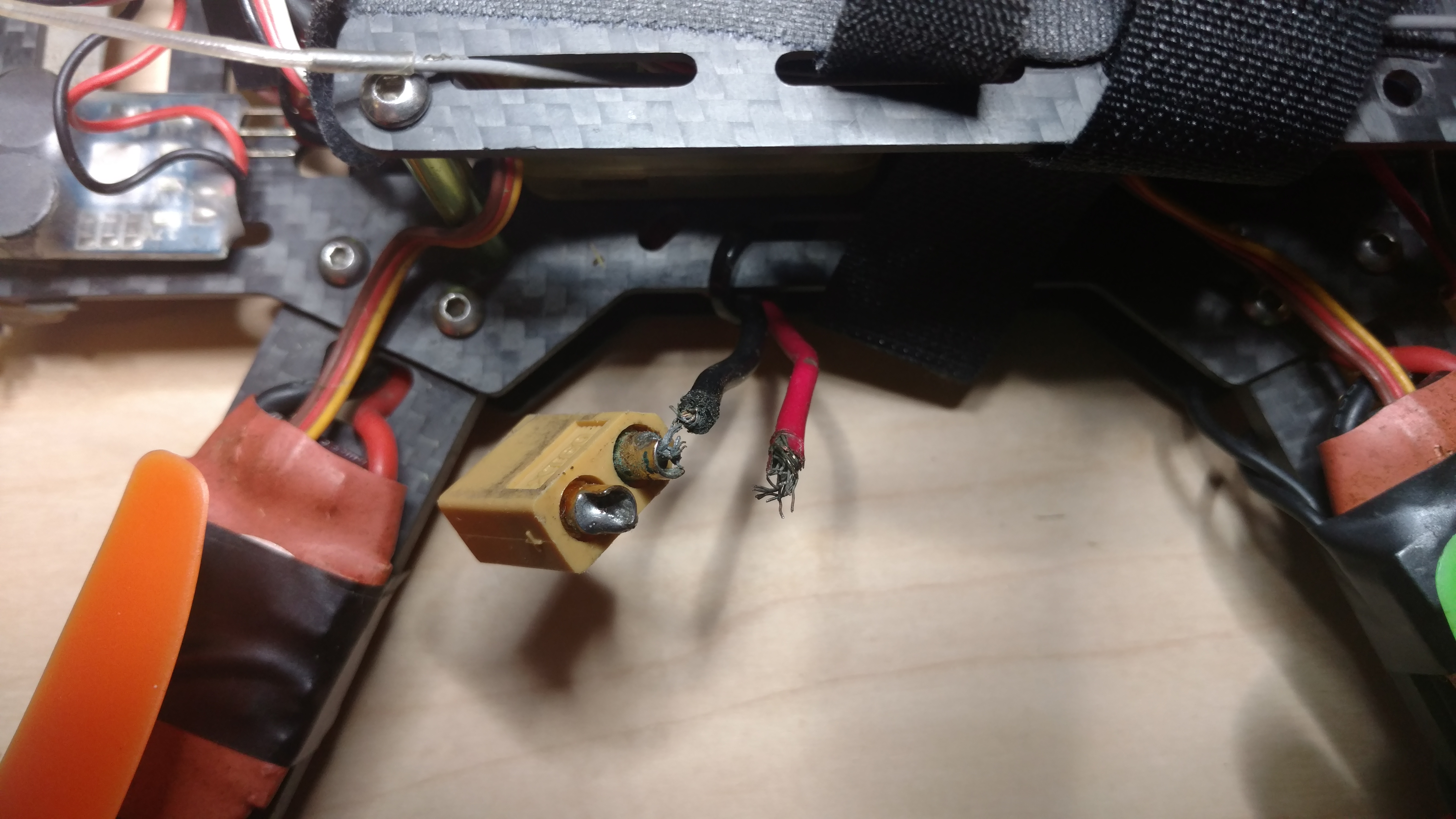
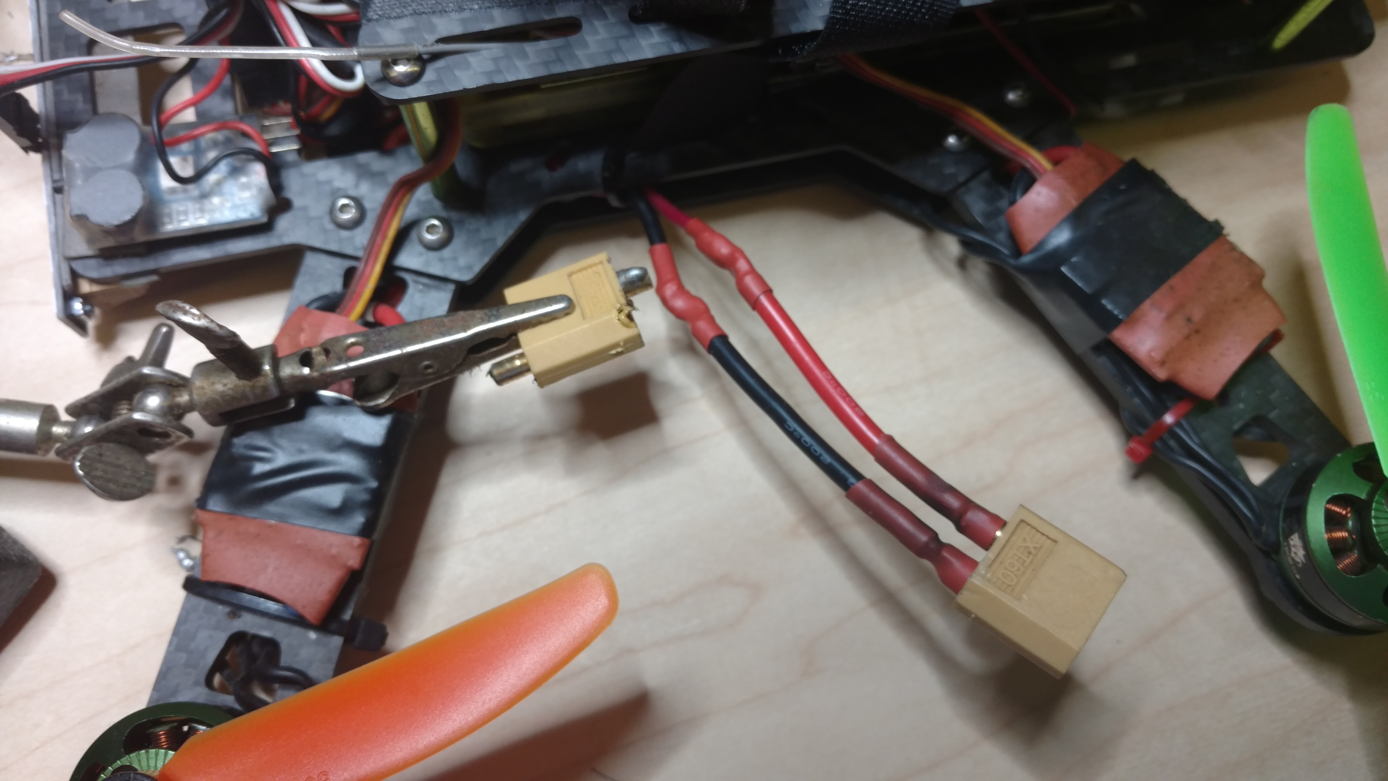
Next step is making that 2.8kWh of 24v power available for use. In the past, using inverters to convert the power from one voltage to another was an extremely wasteful process. But modern inverters are pretty good. I got an extremely cheap 1kw inverter off Amazon that was designed to take 24v and wired it to the battery bank directly. This gave me 120v power running off a set of batteries that are charged exclusively from solar. I was in business.

The complete installation in the shed. RPi not shown.

At this point, it’s important to note that while this all sounds pretty clean and straight forward, there’s a lot of wiggle room to consider. For instance, solar panels are not perfect – not even close. They only produce power when there is sunlight on them. Here in the northeast, that’s not a big part of the day. On a good day I could get 4 or so hours of direct sunlight in the winter. My little single 305w panel was absolutely not going to be able to keep up. I added a second panel, and wired them in parallel (which would double the amperage, but keep the voltage the same). Now I’m doing on a good day about 1.7kwh of power. If my batteries get completely drained, it’ll take a day and a half to refill them. I’ll definitely need more capacity, but I’m not using the batteries for a lot right now, so this is fine.

Two panels installed, the view from my office.

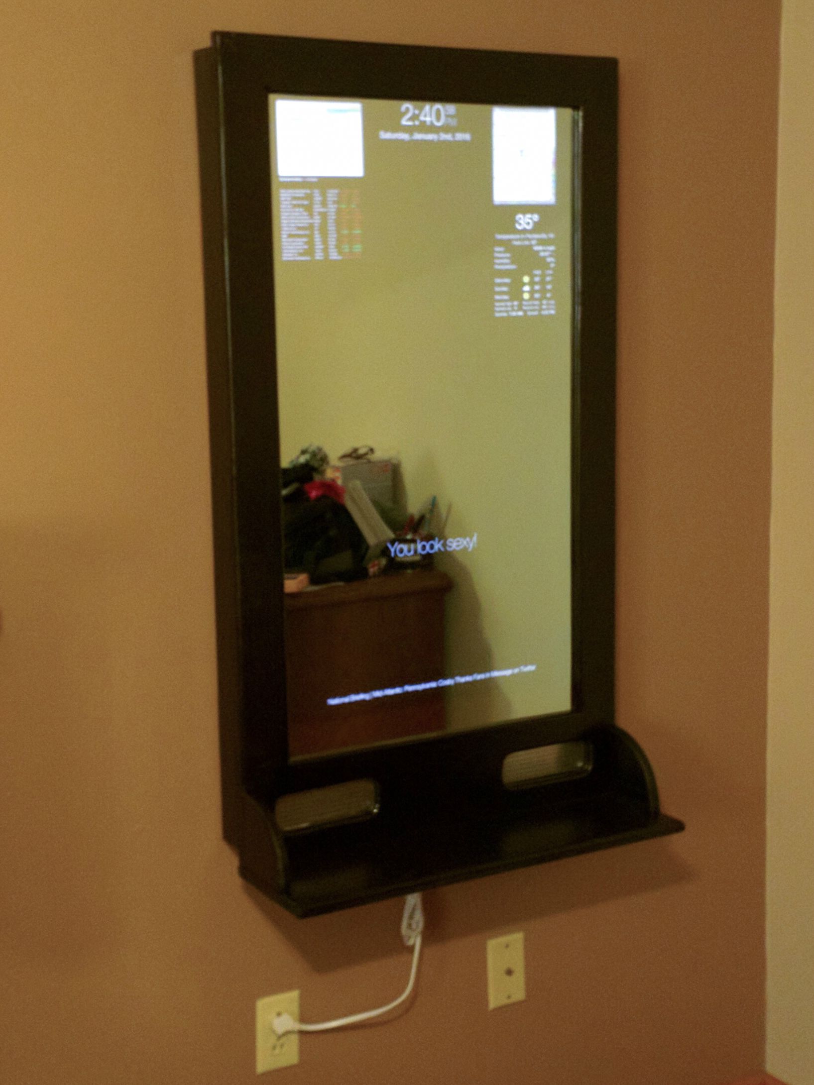
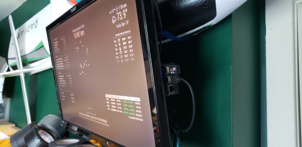
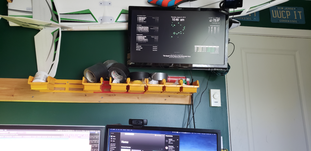
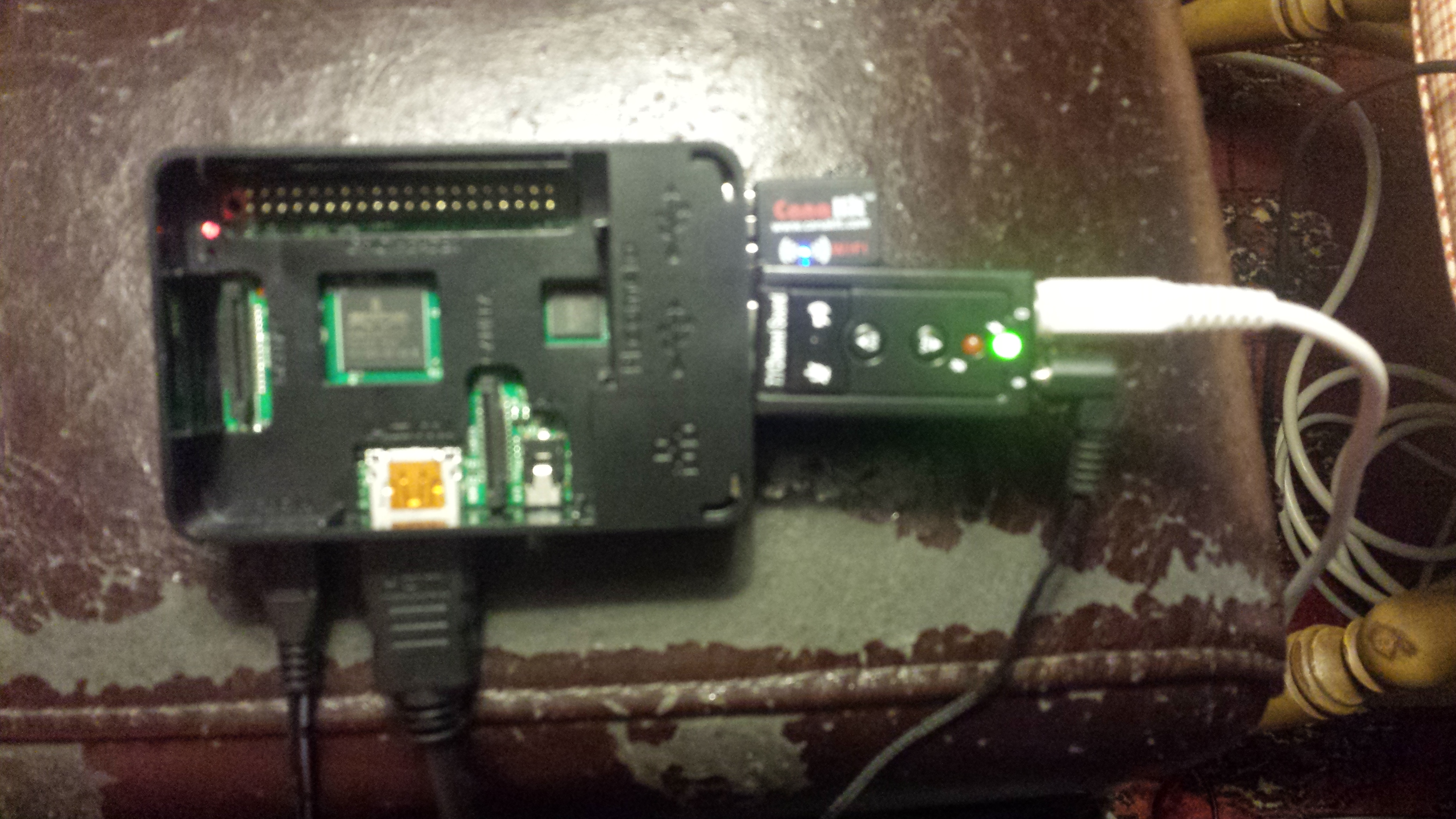
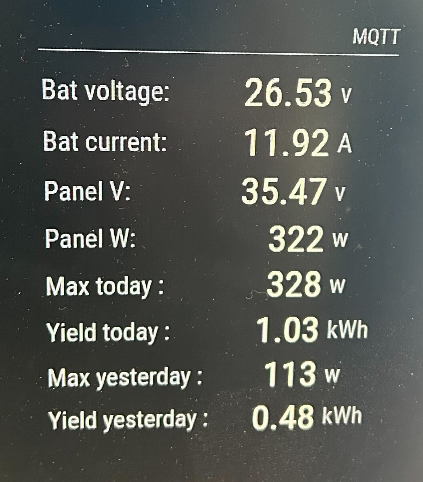
The solar controller I’m using has a bluetooth module that lets it be monitored remotely, but given that this is out in tool shed, and data is available from it only when the phone is attached to it, I needed something a little more realtime. I hooked up a raspberry pi to the controller and set up a small python script to constantly poll the controller for telemetry, which then posts to MQTT. I then added an MQTT polling function to my Magic Mirror – giving me a realtime display of what was happening in the power shed, including maxes for the last 2 days.

Up And Running – And Next Steps

MQTT Display on a sunny day

So far this has been a stable, successful project. Of course, once it was up and running, winter set in, so I spent less time out in my workshed, but I’m looking forward to having it ready for more use. One of the challenges is keeping things cool in the summer. The smallest AC I can find is about 4A@110v, or 440watts. On a sunny day, I can just barely keep up with that, but there’d be something awfully nice about having an AC cooled workshop that’s 100% solar powered.

I’m planning on upgrading the installation this summer to add 2-4 more panels, bringing my total production closer to 1kw. This will unfortunately push past the capacity for my MPPT controller, so that’ll need an upgrade. And of course, I’d love to figure out how to add more batteries fore capacity.

Ultimately I’d love to find a way to wire this into the house. Right now there’s no simple way to do this other than running an extension cord through a window and running some internal gear on it. Short of adding a new panel to house mains and putting a smart switch in place, I may simply need to live with having a secondary power source powering SOME things, separate from the house.

Parts List

Overhead LED Light Replacement for RV Camper Trailer

When we got our 2016 Starcraft hybrid trailer, it felt like a great combination of small size, expandable living space, and conveniences. I mean, we have our own bathroom, shower, AC, heating, and kitchenette. Heaven!

One thing irked me right off the bat though. The internal lighting. The trailer came with round 12v ceiling lights that were blazingly bright. No dimmer, no adjustment, and it was direct lighting – ie, it shined directly on whatever you were illuminating, unlike, say, a table lamp, which uses a shade to diffuse the light.

I decided to replace them.

The Light

After doing some research, I settled on the BlueFire 700LM Dimmable LED dome lights. They offered a couple advantages:

  • They fit the aesthetic of the interior – flush mount, easy to attach
  • These panels are dimmable. You can use the slider to bring the intensity down to whatever you’re looking for
  • They have a ‘temperature’ setting that lets you go from ‘electric blue bright’ to ‘soft yellow’, depending on what you prefer.

Installation

Here’s what the old lights look like. They’re pretty basic, just an on/off switch. There’s about 4 in the interior (I’m not touching the ceiling lights, these are just for the sitting areas)

Uninstalling the light was pretty straightforward. Pop off the cover, unscrew the 4 mounting screws. Of course, that revealed this top notch installation job on the part of Starcraft. Looks like they just poked away at it with a small drill until they could smash a hole. Sigh.

After that, it was just a matter of wiring in the two leads, and screwing the new planel into place. I really like how it looks, and nighttimes are FAR FAR more comfortable now, as I can dim the lights down, put some quiet music on, and relax.

I really like being able to do basic changes to the trailer, upgrading bits and pieces, and slowly tweaking it to something I’m really comfortable in. One big project I’m hoping to figure out is how to make the sitting area more comfortable. Those bench seats around the table are uncomfortable as heck. A project for another time.

PDP-11/70 Retrocomputing Build

Back when dinosaurs roamed the earth, I attended a very technical college to start getting my degree in Computer Science. Note, this wasn’t ‘programming’ ‘systems design’ ‘databases’ ‘AI’ or any of that, no, the industry was young enough that just HAVING a computer science degree was notable.

While the college experience didn’t work out well for me, I have a very strong memory of my first semester (back then the college called them trimesters I believe) walking into the computer science building and seeing a glassed in room with a bunch of racked equipment in it. On the front of one of the racks was a brightly colored panel, with a lot of purple and red switches, and many blinking lights. In the corner, it said PDP-11/70, and I thought it was the coolest thing I had ever seen.

Turns out this machine was used in the undergraduate program to teach students Unix. We had a classroom full of DEC GiGI terminals and students would plunk away at shell scripts, learning ‘vi’ and generally making a lot of beeping noises. There were about 16 terminals, which meant that machine, which was approximately 1/5000’th the speed of a modern Core i7 process (MWIPS 0.535 for the 11/70 vs 3124 for the i7) was supporting 16 concurrent users programming away on remote terminals.

Well, life moved on, and while I did build my own DEC minicomputers, I never actually owned an 11/70. They were temperamental, that were designed to be powered up and left running for years. Not exactly a hobbyist machine.

In the last year or two, some folks have been taking advantage of the SIMH project (a hardware simulation environment) to emulate these old machines, and run the original operating systems on them. When I saw that Oscar had put out a kit for the PiDP-11/70, a fully functional PDP-11/70 front panel that mirrors precisely the original machine, I had to have one.

The kit is powered by a Raspberry Pi-4 loaded with the SIMH package anda . bunch of disk images. The system happily runs any number of old DEC operating systems, as well as Unix 2.11BSD, and various other Unix versions. On bootup, you simply select which disk image you want to run, and after a few moments, you’re looking at an operational console happily booting RSX-11MPlus, RSTS, RT-11, BSD Unix, whatever you’d like.

Total build time was somewhere around 7-8 hours. Imaging and setting up the Pi took about 2 hours (mostly downloading packages), and the actual physical build of the front panel took another 6+ hours.

The experience of using the machine is somewhat surreal. In the past, I spent a lot of time learning Unix and then VMS. I also worked on DEC Pro/350’s for a while, which run a modified RSX-11MPlus, so it feel great to be back in that environment again, but I have so much to re-learn.

Having the delightful blinking lights nearby showing activities in realtime is a delightful way to have a visual representation of the inner workings of computers, something we don’t see a lot of in modern systems.

Here’s some pics of the build in progress. It’s a great addition to the home office collection!

I Built an Evil Genius Sign for Halloween

It’s no secret I’m a huge fan of Warner Brothers cartoons. My sister and I were basically raised on this stuff, and so much of our cultural reference points (and humor) comes from watching Bugs Bunny when we were growing up.

So, as Halloween approached, I thought it might be cool to recreate an iconic image from the 1952 cartoon “Water Water Every Hare”, where Bugs is taken to a big scary castle on the edge of a waterfall. The castle is inhabited by, naturally, an Evil Scientist, who advertises the fact with a blinking sign on the towers of his castle.

Okay, I’m not really a scientist, I’m an engineer, but I figure I could apply a little artistic license and make a sign like that for my house for Halloween.

I wanted it big enough so I could put it in an upstairs window and have it visible from the pathway. We get a LOT of kids through our community over Halloween, and tons of parents as well (since mostly the parents would get the reference), so it needed to be visible. In order to constrain the glare, I decided to put it in basically a shadowbox configuration. An enclosed box, LED lighting inside, with a cutout pattern on front that would show the text.

First step was to use the laser cutter at the Makerspace to cut out the lettering. As anyone who does stencils will recognize, the second line (“BOO”) would have floating elements in it, and would have to be glued down after the box was made.

I found some old acrylic sheeting that still had one strip of white backing on that, and that made a dandy diffuser, as well as a place to mount the center parts of the lettering.

Next, based on the size of the lettering, I whipped up a box out of some scrap wood, and painted it black. I also painted the letter stencils so the shadowmask wouldn’t show up at night, but the lettering shining through would.

The colored lighting was done with some LED strips and an arduino. The sketch was painfully simple. Just first row on, wait a second, off, wait a half second, second row on, wait a half second, off, then wait a half second and then repeat. The most challenging part was soldering up the strips (I needed 3 rows), and mounting the arduino.

The only thing I had to go ‘buy’ was the backing board. A quick trip to Michaels got me a sheet of the plastic corrugated ‘cardboard’ for $4. This stuff is awesome, and I think I’m going to use it more in future projects. I mounted the LED strips and the arduino to it initially using hot glue, but while that’s the default ‘go to’ for DIY projects, I ended up ziptying the strips to the backing board, and doing the same for the arduino. Since the board is flexible, hot glue just didn’t make sense.

Once everything was screwed together, it was just a matter of putting it in the window and plugging it in. Yay! It worked!

I slightly misjudged the width of the window, so it doesn’t quite have the margins I had hoped, but when it got dark, it looked great. Very happy with the end result!

Using Magic Mirror 2 to Create a Dynamic Display / Dashboard

The “Magic Mirror” craze got pretty big in the hacker community a few years ago. For those who may not be familiar with them, a Magic Mirror is setup using a small display behind a 2 way mirror to add text and information to your bathroom (or wherever) mirror. It’s pretty cool, and can be done at very low cost and with only a little bit of tech know-how.

Image result for magic mirror
My display isn’t actually ‘mirrored’, but many people build things like this one.

I’ve always loved having ‘displays’ around my workspace – showing information that doesn’t need to sit on my ‘work’ monitors, but is handy to be able to glance at.  Being able to quickly glance oer and see  dashboards showing system status, or even something showing date, time, and the weather outside.

A few months ago I decided to take one of my spare monitors at home mounted on the wall over my desk and turn it into a permanent display. It would show my current calendar, weather, stock prices, stuff like that. I got to work.

The Hardware

This part is probably the easiest. I used a spare 24″ LCD monitor I had originally mounted to be a sort of TV display. It wasn’t showing anything yet, so I just co-opted it for the Mirror display. It had an HDMI port on it, so it was perfect.

The second component is a Raspberry Pi3 I had lying around from some  other project. This particularly Pi is pretty old, so using it just drive a mostly static display seemed great. This one has a case and power supply. I was able to just stick it to the back of the monitor, coil up a HDMI cable next to it, and I was all set.

A small note here. A second display I built for our Makerspace actually uses the monitor itself to power the Pi, since the monitor had a USB port on it. A USB -> MicroUSB cable meant as soon as the monitor was powered up, the Pi would boot and start displaying information. Pretty handy.

When building up these systems, I highly recommend having a keyboard and mouse to plug into the Pi. You can use an ‘all in one’ wireless keyboard/mouse from Amazon – these are great because you don’t have to deal with the cables (particularly when the monitor is mounted on a wall), and you can just unplug the USB adapter and use the keyboard on another project at any time.

The Software

The needed packages are pretty straightforward:

  • Raspbian – the default Linux installation for the Raspberry Pi. Get this installed and up to date (Run the package manager updater after the install to make sure you have the latest and greatest of everything)
  • Using a command line or the package manager, make sure you have the following secondary tools installed (these are not installed by default):
    • Chromium (apt-get install chromium-browser)
    • npm
    • xdtotool
  • Magic Mirror 2 – This is the core software that will run your display. Follow the directions on installation carefully. Clone the repository and get it ready for use. I use the manual installation procedure , it works best for how I build systems. YMMV.

Configuring the Host

At this point, I’m assuming the manual configuration of the software above has gone correctly, and you’re able to either use the Raspbian browser or Chromium to connect to http://localhost:8080/ on the Pi and view something approaching the display you want.

Now, this is where I’ve seen a lot of tutorials and other reference material fall down. How do you go from a desktop showing your display to something that will survive reboots, auto-configures itself, etc. Well, here’s what I did to make my display boards stable and rebootable without user intervention.

Some of these things are convenience items, some are mandatory.

  • For the love of all that is holy, set your password. The default ‘pi’ password is well known, please reset it. This device will be running unattended for days/weeks/months. Please change the password.
  • Rename the host – this is super handy so you can ssh to it easily. Edit the /etc/hostname file and give it a nice name (mine is ‘mirror’). Once you do this, from your local network, you’ll be able to ssh into the pi via ‘ssh pi@mirror.local’ – neat trick, huh?
  • Create an autostartup script for the Pi that starts the browser in full screen mode just after the desktop loads. Best way to do this is to edit /etc/xdg/lxsession/LXDE-pi/autostart and put the following code in that file:
@xset s noblank 
@xset s off 
@xset -dpms 
@lxpanel --profile LXDE-pi 
@pcmanfm --desktop --profile LXDE-pi 
@xscreensaver -no-splash 
@chromium-browser --app=http://localhost:8080 --start-fullscreen 
  • Create a cron job entry that will cause the magic mirror server software to restart on reboot. Easiest way to do this is use the ‘crontab -e’ command to make a new entry. Add the following line to the bottom of file (note, this assumes that the Magic Mirror software is installed in /home/pi/MagicMirror – adjust if that’s not the case)
@reboot cd /home/pi/MagicMirror;node serveronly > /home/pi/nodeserver.log 2>&1
  • On reboot, your mirror software should come up cleanly. Here’s a small trick though that makes remote maintenance easy. If you make a change to the config of the server – add a new module, change sources, etc, and you’re like me and have long since detached the keyboard and house from the unit, this little command will force the Chromium browser to do a reload, bringing in the changes you make to your config file. No need to reboot!
DISPLAY=:0 xdotool key F5

Conclusions / Sum-up

I’ve been running my display at home, and the second display up at the lab for a few months now. I’ll write some more on a few of the modules I’ve used (hooking up to my home automation stuff has been interesting), but that’ll be in a future article. I love having the date, time, calendar, stock prices, and weather always visible. The news ticker at the bottom has been sort of ‘cute’, but I really don’t watch it that much.

There are literally hundreds of third party modules available for the mirror software. You can configure the layout of the screen to do just about anything – from showing phases of the moon to displaying the next time a bus will stop in front of your office. Enjoy!

Best Amazon Echo Dot Wall Mount Ever

I have 4 Echo Dots, plus a full size Echo in the living room. Love the durned little buggers, and calling out ‘alexa!’ has become a normal part of every day life. I use it for music, news, shopping lists, and home control of lights and dimmers. I can see the days of carrying on conversations with your house getting closer and closer.

The Dots are cute, but they need to sit on a surface somewhere. That takes up space and clutter. I’d been digging around to try and find a 3d printed mount or something similar so I could mount the Dots on the wall.

This morning while cleaning up my workbench, I realized there was a very simple way of hanging the dot on the wall. A pair of 3″ framing nails later, and voila. The dot is up and off my workbench, it’s stable, the speaker is cleared enough to be heard and sounds fine, victory.

I know many people dont’ have 2×6 studs exposed everywhere, but goshdarnit, this was a quicky fix that works great.

Creating Timelapse Videos from a Synology NAS

About a year and a half ago, I bought a Synology 216+ NAS .  The primary purpose was to do photography archiving locally (before syncing them up to Amazon S3 Glacier for long term storage).  The box has been a rock solid tool, and I’ve been slowly finding other uses for it.  It’s basically a fully functional Linux box with an outstanding GUI front end on it.

One of the tools included with the NAS is called ‘Surveillance Station’, and even though it has a fairly sinister name, it’s a good tool that allows control and viewing of IP connected cameras, including recording video for later review, motion detection, and other tidbits.  The system by default allows 2 cameras free, but you can add ‘packs’ that allow more cameras (these packs are not inexpensive – to go up to 4 cameras cost $200, but given this is a pretty decent commercial video system, and the rest of the software came free with the NAS, I opted to go ahead and buy into it to get my 4 cameras online).

It just so happens, in September, 2017, we had a contractor come on site and install solar panels on several houses within our community. What I really wanted to do is use the Synology and it’s attached cameras to not only record the installation, but do a timelapse of the panel installs. Sounds cool, right?

Here’s how I did it.

The Cameras

The first thing needed obviously were cameras. They needed to be wireless, and relatively easy to configure. A year or two ago, I picked up a D-Link DCS-920L IP camera. While the camera is okay (small, compact, pretty bulletproof), I was less than thrilled with the D-Link website and other tools. They were clunky and poorly written. A little googling around told me “hey, these cameras are running an embedded OS that you can configure apart from the D-Link tools”. Sure enough, they were right. The cameras have an ethernet port on them, so plugging that into my router and powering up let me see a new Mac address on my network. http://192.168.11.xxx/ and I got an HTTP authentication page. Logging in with the ‘admin’ user, and the default password of… nothing (!), I had a wonderful screen showing me all the configuration options for the camera. I’m in!

First thing, natch, I changed the admin password (and stored it in 1Password), then I set them up to connect to my wireless network. A quick rebooot later, and I had a wireless device I could plug into any power outlet, and I’d have a remote camera. Win!

Next, these cameras needed to be added to the Synology Surveillance Station. There’s a nice simple wizard in Surveillance Station that makes the adding of IP camera pretty straighforward. There’s a pulldown that lets you select what camera type you’re using, and then other fields appear as needed. I added all of my cameras, and they came up in the grid display no problem. This is a very well designed interface that made selecting, configuring, testing, and adding the camera(s) pretty much a zero-hassle process.

If you’re planning on doing time lapses over any particular length of time, it’s a good idea to go into ‘Edit Camera’ and set the retention timeperiod to some long amount of time (I have mine set to 30 days). This’ll give you enough room to record the video necessary for the timelapse, but you won’t fill your drive with video recordings. They’ll expire out automatically.

At this point you just need to let the cameras record whatever you’ll be animating later. The Synology will make 30 minute long video files, storing them in /volume1/surveillance/(cameraname).

For the next steps, you’ll need to make sure you have ssh access to your NAS. This is configured via Control Panel -> Terminal / SNMP -> Enable ssh. DO NOT use telnet. Once that’s enabled, you should be able to ssh into the NAS from any other device on the local network, using the port number you specify (I’m using 1022).

ssh -p 1022 shevett@192.168.11.100

(If you’re using Windows, I recommend ‘putty’ – a freely downloadable ssh client application.)

Using ‘ssh’ requires some basic comfort with command line tools under linux.  I’ll try and give a basic rundown of the process here, but there are many tutorials out on the net that can help with basic shell operations.

Putting It All Together

Lets assume you’ve had camera DCS-930LB running for a week now, and you’d like to make a timelapse of the videos produced there.

  1. ssh into the NAS as above
  2. Locate the directory of the recordings.  For a camera named ‘DCS-930LB’, the directory will be /volume1/surveillance/DCS-930LB
  3. Within this directory, you’ll see subdirectories with the AM and PM recordings, formatted with a datestamp.  For the morning recordings for August 28th, 2017 ,the full directory path will be /volume1/surveillance/DCS-930LB/20170828AM/.  The files within that directory will be datestamped with the date, the camera name, and what time they were opened for saving:
  4. Next we’ll need to create a file that has all the filenames for this camera that we want to time.   A simple command to do this would be:
    find /volume1/surveillance/DCS-930LB/ -type f -name '*201708*' > /tmp/files.txt

    This gives us a file in the tmp directory called ‘files.txt’ which is a list of all the mp4 files from the camera that we want to timelapse together.

  5. It’s a good idea to look at this file and make sure you have the list you want. Type
    pico /tmp/files.txt

    to open the file in an editor and check out out.  This is a great way to review the range of times and dates that will be used to generate the timelapse.  Feel free to modify the filename list to list the range of dates and times you want to use for the source of your video.

  6. Create a working directory.  This will hold your ‘interim’ video files, as well as the scripts and files we’ll be using
    cd 
    mkdir timelapse
    cd timelapse
  7. Create a script file, say, ‘process.sh’ using pico, and put the following lines into it.  This script will do the timelapse proceessing itself, taking the input files from the list creatived above, and shortening them down to individual ‘timelapsed’ mp4 files. The ‘setpts’ value defines how many frames will be dropped when the video is compressed. A factor of .25 will take every 4th frame. A factor of .001 will take every thousandth frame, compressing 8 hours of video down to about 8 seconds.
    #!/bin/bash
    
    counter=0;
    for i in `cat /tmp/files.txt`
    do
        ffmpeg -i $i -r 16 -filter:v "setpts=0.001*PTS" ${counter}.mp4
        counter=$((counter + 1))
    done
  8. Okay, now it’s time to compress the video down into timelapsed short clips.  Run the above script via the command ‘. ./process.sh’.  This will take a while.  Each half hour video file is xxx meg, and we need to process that down.  Expect about a minute per file, if you have a days worth of files, that’s 24 minutes of processing.
  9. When done, you’ll have a directory full of numbered files:
    $ ls
    1.mp4
    2.mp4
    3.mp4
  10. These files are the shortened half hour videos.  The next thing we need to do is ‘stitch’ these together into a single video.  ffmpeg can do this, but it needs a file describing what to load in.  To create that file, run the following command:

    ls *.mp4|sort -n| sed -e "s/^\(.*\)$/file '\1'/" > final.txt
  11. Now it’s time to assemble the final mp4 file.  The ‘final.txt’ file contains a list of all the components, all we have to do is connect them up into one big mp4.
    ffmpeg -f concat -safe 0 -i final.txt -c copy output.mp4
  12. The resulting ‘output.mp4’ is your finalized video.   If you’re working in a directory you can see from the Synology desktop, you can now play the video right from the web interface.  Just right click on it, and select ‘play’.

Here’s two of the three timelapses I did, using a remote camera in my neighbors house.  Considering the low quality of the camera, it came out okay…

This entire tutorial is the result of a lot of experimentation and tinkering.  There are holes, though.  For instance, I’d like to be able to set text labels on the videos showing the datestamp, but the ffmpeg that’s compiled on the NAS doesn’t have the text extension built into it.

Let me know if you have any suggestions / improvements / success stories!

Repairing Drone XT60 Power Connectors

A quicky post here. I took about a year and a half off drone racing, and I’m just getting back into it for a bit. What has happened during that time is that the community has moved onto to faster, smaller drones. At the moment all I have is my 250mm QAV250 clone, so keeping that flying until I build a new machine is what’s keeping me busy.

The damaged XT60

I went out to fly yesterday with some folks in Waltham, but before I could power up, I noticed my XT60 connector had broken loose on the positive lead. Bad news. That’s not something I can fix in the field. No flying for me!.
Tonight I sat down to repair the power connector, but realized I didn’t have any spares. I tried to reuse an old connector, and… well, melted it into goo. (that’s what’s int he alligator clips in the picture below). I had one other one, and managed to desolder and solder in the new connection without too much damage. I am sort of proud of the fact that I was able to reconnect the power leads, and add 3″ of extra silicone insulated feed wire, and get my shrink tubing in place without much chaos.

All fixed and insulated properly.

Tomorrow I should be able to fly with the MultiGP folks up in Derry, but I know my time with the 250 is coming to an end. I have a new frame and motor and battery setup in mind, but more on that when things get closer. For now, things are packed up and ready to go flying tomorrow!

Using Amazon Kindle Fire HD’s as Registration Terminals

Even though I’m not working on CONGO as much anymore, I’m still helping out with registration at a couple events, and I’m always looking for better tools and gear to use. I originally designed registration to use cheap, network bootable PC’s, but that was so 15 years ago. The new hotness are small, inexpensive tablets. So could you put together a registration environment using some cheap tablets? Sure.

I’m helping an event that’s using EventBrite for registration services. I’d helped out at a different event about a year ago, and was impressed with the tools Eventbrite offered. The best part was the Eventbrite Organizer, a mobile app for IOS and Android that basically gave you a live dashboard, but also allowed super-fast checkins using a QR code scan. Think of scanning a boarding pass when boarding an airplane. The process is very similar.

The only drawback was, I needed a series of tablets that were roughly the same (bringing batches of workstations that are all different is a sure way to headaches). I didn’t think buying a stack of iPads was going to make sense, and el cheapo tablets from ebay and amazon are sketchy.

3 Kindle Fires being configured as registration terminals
I saw a deal come across Woot for Amazon Fire HD 7″ Tablets for… $33. Each. After digging around on the net, it looked like it was possible to load non-amazon software on these, it just took a little bit of jiggling. I’ve rooted Android tablets before, but it’s not a pleasant experience. I was seeing documentation that allowed for the Play store to be activated without a lot of yak shaving, so I decided to go all in.

I ordered 3 of the tablets, and they arrived a few days later.

First impressions – these are really nice. The design and polish is excellent, they fit well in the hand, and have exceptional screens. They have excellent battery life, and front and rear facing cameras. For $33, there’s not much to go wrong with here.

Here’s the steps I went through to get them up to ‘useable’ status.

  • First, charge them up, natch. They have great batteries, and the entire upgrade process and installation can happen on battery, but really, just get ’em charged.
  • Next, power up and log into your Amazon account. All the Fires have to be tied to an amazon login. Using the same one on each is fine (Amazon supports many Kindles per account).
  • Continuously go into the System settings (swipe down from the top) and select Device Information -> System Update. There’s a good 6 full OS updates that have to happen to bring your device up to FireOS 5.3.x or later. This can take upwards of an hour and a lot of reboots, but at the end, you’ll have a fully upgraded device.
  • Next, we’re going need to install APK’s that are not ‘blessed’, so you have to tell the Fire to accept them. Go into settings -> Security settings and check the switch that says “Allow third party apps”
  • Download and install a file manager. I used ES-File Explorer, which is very popular, but I’ve seen others say “don’t use this it doesn’t work”. I suspect the ‘not working’ has since been fixed. It’s worked fine on 3 devices so far.
  • Next, pull down the APK’s via the Fire’s Silk Browser. Go to this thread on the XDA Developers forum and click on each of the APK links, and download the files, in order, from top to bottom.
  • Once they’re downloaded, start up the ES File Explorer, and navigate to the Downloads folder. You’ll see 4 APK’s there. Click on the them from RIGHT TO LEFT (which will install the ‘oldest’ one first, and the Play store last.
  • After each of the APK’s is installed, launch the Play store, log in with your Google account, and you are all set.

Now that the Fire can install third party apps via the Play store, all we needed to do is install Eventbrite Manager, and log into it with an access-limited login we created just for this event (we’re going to allow general joe schmoes to check people in, and having access to refunds, people’s personal infromation, etc – didn’t seem like a good idea. So a generic Eventbrite login that ONLY allows for checkins was created, and that’s what we logged the tablets into.

I also picked up a handful of desk mounts with really strong gooseneck stalks. Because we’re going to be scanning receipts via the rear camera, the tablet needs to be held off the desk easily.

And we’re done! The Eventbrite Manager app syncs the attendee list whenever it’s connected to the internet. So we can go ahead and check in people super-fast (with a very satisfying BADEEP whenever a successful scan happens), and not have to rely on hotel internet connectivity (which can be notoriously sketchy). At the end of the day, we have a full record of everyone who has checked in and when.

I Played With Lasers, and I Liked It

It’s no secret I’ve been having a great time hanging with the folks at MakeIt Labs in Nashua, NH. Many of the projects I’ve been working on have only been possible with their help and collaboration. Not in a “here lets do this for you” sense, but in providing a community where ideas can be bounced around, coupled with a physical space with every tool a geek could ever need at hand.

I’ve unofficially become the person organizing the parts supplies. These are ranks and ranks of bins that hold everything from capacitors to stepper motors to hot glue sticks to arcade pushbuttons. Understandably, these things can easily get out of control, so constant pruning and management is sort of a requirement. I can do that!

80w CO2 Laser in use
A new set of drawers we picked up are super-handy, but they’re just empty metal boxes. About 10″x12″x4″. Nice, useful, and stackable, but we tend to store lots of little parts, so we need to be able to divvy up that space a little more. We needed something like trays that could go into the drawers (which are all about the same size), to store small parts. The tray should be easily removable (take the tray out, use some of the parts, put it back), and easy to make many of them. We have about 120 drawers that need inserts. This sounds like a job for our 80w CO2 laser!

I had done some basic work on the laser, but this would be my first ‘build from scratch’. After measuring out the drawers, I decided to make a 9″square baseplate, with 4 sides, and a single divider down the middle that could easily be picked up. I used Adobe Illustrator to set where the cuts would be (Illustrator is great primarily because drawings measured in it translate perfectly to the laser cutter. No scaling / stretching problems. When I say ‘cut something 9″x9″‘, what I get is something 9″x9″.)

I manually did all the crenelations where the pieces would fit together. A fellow maker pointed out there’s software that helps do this, but for this first runthrough, I was okay doing it by hand. The material I was using is 1/8″ acrylic sheeting. Somewhere the lab picked up a metric buttload of the stuff, so we literally had dozens of square meters to work with.

First complete cut of the tray inserts.
Total cutting time was about 3 minutes. The laser had no problems working with the material. After removing the pieces from the machine and taping them together, I had a mocked up tray insert! Hooray!

It wasn’t all peaches and cream. I did mess up measurements on two of the tabs, and forgot to put in a cutoff for one small extension. After assembling what I’m referring to as the ‘1.0’ version, I realize there should be some changes. The central divider should tuck under the end pieces to give it better strength (it’s slotted in on the top now), and I should make a version of this that has 3 spaces in it, not just two. Tighter tolerances on the slots are needed (I measured 1/8″, but the ablation from the laser takes off a little bit more, so the slots are wider than they need to be).

Next step will be to re-do the cuts with the supporting tabs, remove the paper from the acrylic, and glue things together. If all goes well, I’ll have a nice insertable tray, and the ability to crank out many more without much work. Going full-on production of over a hundred of these trays will require an inventory of how much acrylic we have, and a decision on if we want to just pick up a few dozen sheets of 1/8″ birch (which would negate the ‘peeling off the paper’ problem).

I’ll post when there’s an updated sample. But for now… I played with lasers, and it was awesome.

Using a Raspberry Pi as a Realtime Voice Changer for Halloween

As most readers know, I’ve been working on my magic staff project for the last year and a half. I incorporated into the ‘Technomancer’ costume for Halloween and Arisia last year, and it was a big hit. I’m continuing to expand the costume, and one thing I’ve always wanted was a voice changer that would let me have a nice sepulchral voice to go with the creepy visage. My own voice from behind the mask is extremely muted, so it’s hard to carry on conversations or even talk to someone, so some external hookup was needed.

My 'bench' test run of the Pi with external USB sound board.
My ‘bench’ test run of the Pi with external USB sound board.

What surprised me was… no one had done this. I searched all over the web for realtime voice processing setups using a Raspberry Pi or Arduino, and while some folks had come close, no one (that I found) had put all the pieces together. So, it was time to do it!

The first component is naturally a Raspberry Pi. I used the pretty awesome CanaKit, which included lots of goodies (most importantly a good, solid case for the board, as well as a microSD card and other accessories). $69 was a great price.

Next, the Pi has onboard audio, but… well, it sucks. I needed separate mic input and outputs, and off-CPU sound processing. Fortunately, there’s huge numbers of these USB sound adapters going for less than $10 a pop. I got 2 just to be careful.

(Update 8/2022 : Since this article was written, obviously things have changed a lot.  Modern Pi4’s are the current best practice.). Pi4’s also have a much better sound board, so an external USB audio stick shouldn’t be necessary.

Pyle Audio portable PA

Next, I needed an amplifier. Something portable, loud, and with a remote microphone. This is one just for my setup. Obviously whatever you choose for your own project, pick whatever audio options you’d like. THe sound adapter has standard 1/8th” jacks for mic in and audio out, so just plug right in (I had a small problem with my Mic connection, in that the mic cable I used needed to be ‘out’ a quarter inch to connect properly. I used a small O-ring to keep the spacing proper). The amp I used is Pyle Pro PWMA50B ‘portable PA system’. At $29, it’s well worth it. Comes with a mic, built in rechargeable batteries, a belt mount, and, most importantly, an Auxiliary input.

Now comes the hard part. Getting the audio set up so it could handle recording and playing back in realtime required installing the ‘sox’, toolset, as well as all the alsa tools (most of ALSA comes with the Pi, but make sure they’re there). First, make sure you can play audio through the USB card to the PA. I used ‘aplay’ for this (this ALSA simple player), and a small WAV file I had lying around.

I also recommend running ‘alsamixer’ beforehand, to make sure you can see all the devices, and they’re not muted. ‘aplay -l’ and ‘arecord -l’ are handy in making sure you’re seeing everything you need.

Assuming you have working audio, now comes the fun part. Set up a sox pipe to read from the default audio device and write to the default audio device. Like this:

play "|rec -d"

If all goes well, you should be able to speak into the microphone, and have it come out the speaker. There will almost certainly be a delay of anywhere from a tenth to a half a second. There’s ways to mitigate that, but we’ll get to that in a minute.

If you have that path working, you’re 90% of the way done!

For my costume, I needed a deep voice, so I added -pitch -300 like this

play "|rec -d pitch -300"

I also had a problem with a very high pitched whine coming through the speakers, so I added a band filter to remove that (this syntax means “Remove sound centered on 1.2khz, with a bandwidth of 1.5khz on either side”) :

play "|rec -d pitch -300 band 1.2k 1.5k"

Only a little more tweaking, adding some echos, and I had the voice I wanted. The –buffer command shortens how much data is buffered for processing. This helped cut down the delay a bit, but runs the risk of buffer overruns if you talk a lot.

play "|rec --buffer 2048 -d pitch -300 echos 0.8 0.88 100 0.6 150 .5 band 1.2k 1.5k"

Here’s a sound sample of what it sounded like. Note this is before I added in the band filter, so you can hear the whine…

(direct link here)

The last thing needed was to have the changer start up when the pi reboots. I’m planning on carrying the Pi in a pouch on my belt, powered via one of those cell phone external battery packs. I can’t log in and start the tool whenever it boots. The fix is to put the ‘play’ and other amixer commands into a simple shell script (I put it in /root/setup.sh), and using the @reboot entry that the Pi’s version of Linux supports, add this line to root’s crontab:

@reboot sh /root/setup.sh > /root/sound.log 2>&1

Rebooting now works without a monitor and keyboard attached, and the sound processor starts right up. Ready to go!

Leave a comment if you have any questions, this post will be updated as I continue work on the system…

OwnStar – Vulnerability in OnStar Application for GM vehicles

Hack of OnStar Remotelink lets attacker unlock, remote-start, and track cars.

The OwnStar device can detect nearby users of the OnStar RemoteLink application on a mobile phone and can then inject packets into the communication stream to the phone, getting it to give up additional information about the user’s credentials. Those credentials can then be used to gain access to the vehicle’s OnStar account and the full functionality of the OnStar RemoteLink app.

Kamkar says the vulnerability is in the app itself and not the OnStar hardware in GM vehicles. He added that GM and OnStar are working to correct the flaw in the vulnerable mobile application. GM customers who use OnStar can protect themselves for the time being by not using the RemoteLink app.

Good thing I don’t have a GM vehicle that heavily uses OnStar remote services.

Source: ArsTechnica

The Technomancer at Arisia!

This past weekend I packed up and headed to Arisia to work, play, socialize, and, finally put all the costume elements together and become… THE TECHNOMANCER.

The Technomancer!
The Technomancer!

This was the final unveiling of the entire costume the magic staff was created to drive. I’d been adding parts and components for weeks, waiting for others to come in, etc – and in the last week, it all came together.

In summary? It went GREAT. Lots and lots of awesome feedback, oohs and ahs, and tons of geeky conversation around the staff and other parts of the costume. I did learn a lot about what works and what doesn’t work when doing a costume this involved, and while I’m nowhere near done, I’m at a point where I can pick up all the pieces and go to an event, and I’m pretty sure it’ll work well.

Here’s a rundown of everything I added to make the full image work:

  • First, thanks very much to Starlit Creations for making a custom ‘wizards robe’ for my 6’6″ form. She did a great job, exactly to my specs, and it fit me wonderfully.
  • The second big add was a UVEX “Bionic” (yeah, not my name, sorry) faceshield.  I’d been digging around for some sort of ‘mask’ that I could mirror and cover my face, giving that ‘blank look’.  After looking at various environmental filter systems and masks, this shield was exactly right.
  • I added a sheet of ‘one way’ reflective film on the inside of the mask – this turned out to be tremendously difficult as the faceshield needs to flex both horizontally and vertically when being installed, so I couldn’t set the film on the surface while it was on the flat, I had to do it while it was installed, which ended up with some bubbles and wrinkles.  All in all not bad, but I’d like to try to get it perfect.
  • A turtleneck shirt to hide ‘skin’ showing on the neckline, and hide my arms.
  • A pair of black leather driving gloves
  • An extra long belt from my SCA garb
  • My boots from said SCA garb
  • Two lengths of light green lit EL wire and battery packs.  These unfortunately were a disappointment.  Not very bright, and awkward to work with.  I’ll be reworking this part of things.

All assembled, it felt comfortable, looked great, and I was ready to go out in public.

A couple things became apparent really fast…

  • If a person can’t make eye contact with you, they’re nervous and aloof.  They couldn’t see my face – and at least in US culture, the first part of a conversation is making eye contact, which is sort of like “Is it okay to talk to you?” – I guess that’s sort of the point of the ‘faceless’ costume – to make people a little uncomfortable.
  • The mask made it very hard for me to speak loud enough for people to hear me.  Sometimes if I got into a geeky conversation, I’d just flip the mask up – which, naturally, destroys the presentation.  I’m considering a voder-type arrangement moving ahead so I can talk and people will hear me.
  • The mask / hood arrangement can get hot.  Here’s a little secret, I was actually wearing shorts under the robe – so that part was nice and cool (and no one noticed), but I may need to come up with some sort of air circulation solution for the mask.
  • Also, the hood and mask pretty much eliminated my peripheral vision.  Might need to work on that part.
  • The gloves made it hard to feel where the control buttons on the staff were.  That’s definitely up for a change.

I wore the costume and staff for a few hours on Saturday night, and had lots of people taking pictures.  The pic above is from the hotel room before I went out (when I was out in public, the hood was actually pulled forward much more) – but you get the idea.  The EL wire is barely visible 🙁

I have tons and tons and TONS of ideas moving forward, all workable within this costume design (vast improvements on the staff, some small changes to the robes and mask), but for a first time out, I’m pretty psyched!

Arduino Nano “Programmer Not Responding” on a Mac

Arduino Nano v3
Arduino Nano v3

For the Staff project, I’m going to be replacing the existing Arduino Uno R3 with a smaller, more easily embedded Arduino Nano.  The Nano is a heck of a lot smaller than the Uno (makes sense – it’s meant to be permanently installed, while the Uno is a prototyping platform).  I received my Nano a few weeks ago, but immediately ran into a frustrating problem… code would compile, begin to upload, and I’d get the error “stk500_recv(): programmer not responding”

The intarwebz are full of people reporting this problem, unfortunately most are not finding answers.

I went through the usual debugging problems – changing out the USB cable I was using, checking to make sure USB drivers were correct – I could still upload and use code on my Uno, but the Nano flat out refused to accept the new code (and I did check the very common problem of not selecting the correct board in the IDE).

Finally, came across a general discussion about bootloaders, and there was a comment that sometimes these boards do not reset properly.  After some more research, I found some folks using various ‘reset button’ hacks to sort of nudge the board into accepting code.  With a lot of trial an error, I have a procedure that seems to work pretty consistently.  There’s occasional twitches, but with persistence it always loads.

Continue reading “Arduino Nano “Programmer Not Responding” on a Mac”